90-Degree Phase Shifter

For my microwave design class in Spring 2025, I took on an RF design challenge: crafting a 90-degree digital phase shifter bit for S-band weather radar phased arrays. Using Keysight ADS and Rogers RO4003 substrate. Here’s the story of my design journey.
The Mission
As a “design engineer” exploring phased arrays for next-gen weather radars, my job was to build a phase shifter bit operating from 2700 to 3000 MHz. The requirements were clear:
- Microstrip on Rogers RO4003 (20 mil thick, ½-ounce copper cladding).
- Up to two Skyworks DSG9500 PIN diode switches, modeled per Pozar’s equivalent circuits.
- A reflection phase shifter topology inspired by Pozar’s Figure 11.13.
- Tight specs for impedance, return loss, insertion loss, and phase shift.

These specs called for excellent impedance matching, low signal loss, and precise phase control across both diode states, all while ensuring a manufacturable design.
My Custom Topology
I started with Pozar’s reflection phase shifter topology (Figure 11.13), which uses PIN diodes to toggle reflective loads for phase shifts. But I wanted to shake things up, so I made two key changes:
- Open-Circuit Stubs: Replaced short-circuit stubs with open-circuit stubs to simplify fabrication and tweak the reflection properties for my design.
- Series Diodes: Switched from shunt to series diodes because, well, I felt like switching things up! This let me control the signal path directly through the diodes’ on/off states, adding a fresh twist to the phase shift mechanism.

These mods gave my design a distinct flavor while still delivering the required 90-degree phase shift.
My Approach
I brought the design to life in Keysight ADS with a step-by-step process:
Schematic Design: I built a microstrip circuit with two series PIN diodes, open-circuit stubs, and 0402 discrete components (e.g., Murata capacitors/inductors). The diodes were modeled using Pozar’s Fig. 11.6 parameters (Ci=0.025 pF, Li=0.2 nH, Rf=4.0 ohms, Rr=5.0 ohms), and I added T-junctions and discontinuities for accuracy.

Simulation: I simulated from 2500 to 3200 MHz, including ~1/8-inch 50-ohm input/output lines. I fine-tuned stub lengths and component values to nail the specs.
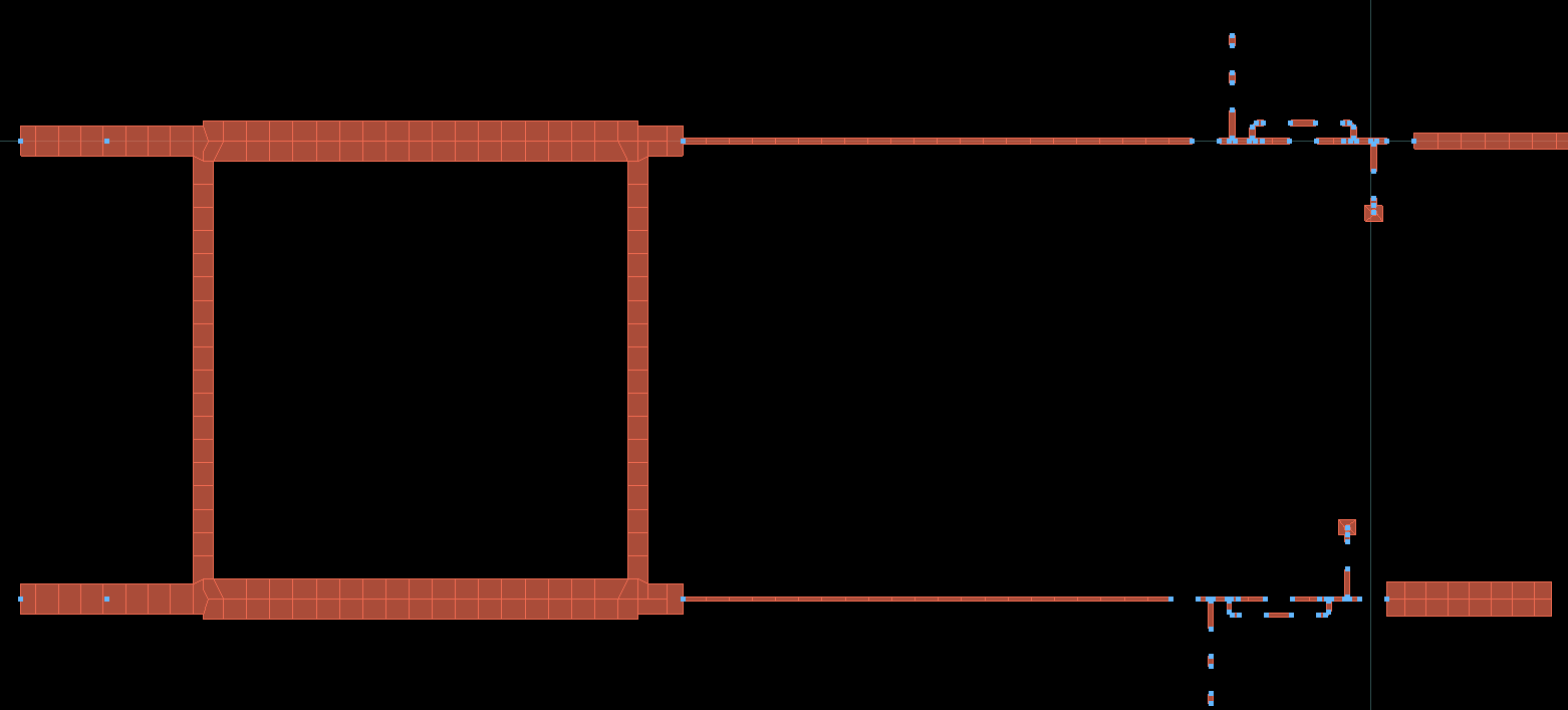
Layout: I created a physically realizable layout, ensuring no gaps or overlaps, with DC bias circuitry for the diodes and line widths above 4 mils.

EM Co-Simulation: I ran Momentum simulations to check real-world performance, though only the schematic needed to meet the specs.
Results
The schematic simulations hit all the marks:
- Return Loss: S11, S22 < -15 dB in both diode states, ensuring great impedance matching.
- Insertion Loss: S21 > -0.7 dB, minimizing signal loss.
- Phase Shift: Differential phase of 90° ± 4.5°, spot-on for beam steering.

Caption: S-parameter and phase plots, verifying return loss, insertion loss, and 90° phase shift over 2700–3000 MHz for both ON and OFF states of the switch.
The EM co-simulation, while not required to meet specs, confirmed the design’s robustness, capturing substrate effects and parasitics. The layout was ready to roll for fabrication, with my series diodes and open stubs fitting perfectly.
Takeaways
This project was an RF design blast! Switching to series diodes just to mix things up led to some fun experimentation, and open-circuit stubs proved a smart move for simplifying the build. ADS tools like LineCalc and Momentum were key for optimizing impedances and verifying EM performance. Bouncing ideas around on the Ed Discussion forum helped me perfect my mods.