Designing a Broadband 90-Degree Hybrid Coupler for Microwave Applications
As part of my coursework in Microwaves at ASU, I tackled an exciting design project: creating a broadband 90-degree hybrid coupler using the double-box branchline topology. The goal was to design a device operating over the 3.4 to 4.2 GHz frequency range, implemented on a Rogers RO4003 substrate (20 mil thick with 1-ounce copper cladding). This project was a deep dive into microwave circuit design, simulation, and fabrication preparation using Keysight ADS. Here’s a rundown of the process and results!
Project Requirements
The design had to meet the performance specifications, outlined in the table below:
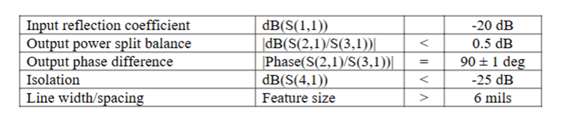
These specs guided every step of the design, from initial simulations to final verification. The challenge was to achieve a low input reflection (S11 < -20 dB), balanced power split between ports (|S21/S31| < 0.5 dB), a precise 90° ± 1° phase difference, and strong isolation (S41 < -25 dB), all while keeping line widths and spacing above 6 mils for manufacturability.
Design Approach
I followed a structured approach recommended in the project guidelines:
- Schematic Simulation: I started with a schematic in ADS using ideal transmission line components to model the double-box branchline topology. This step allowed me to optimize the design for the target frequency range and specs.
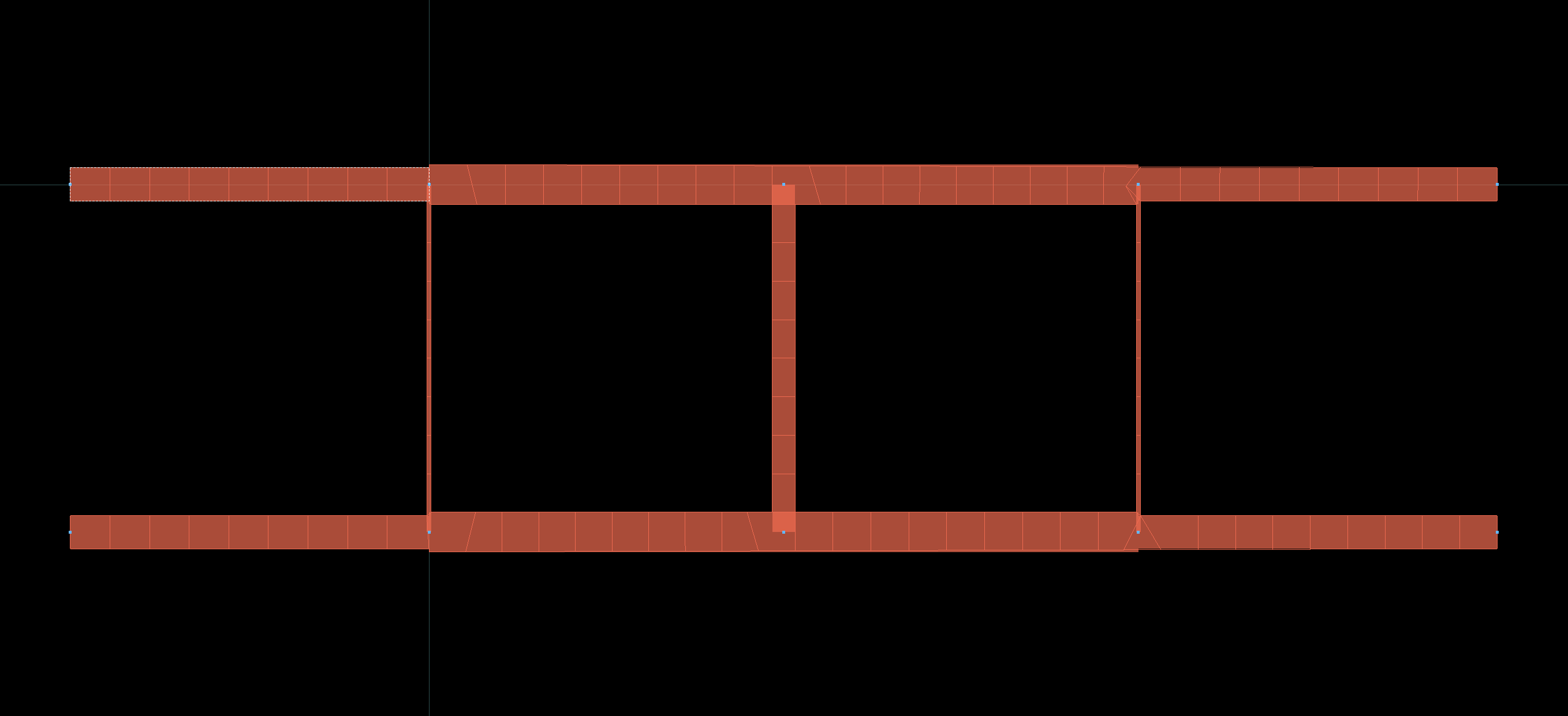
- Microstrip Implementation: Next, I replaced the ideal components with microstrip transmission lines, incorporating discontinuity models (e.g., T-junctions and bends) to reflect real-world behavior. This required re-optimization to account for parasitic effects.
- Layout Generation: Once the schematic met the specs, I generated a physical layout in ADS, ensuring all feature sizes exceeded 6 mils.
- EM Cosimulation: Using Momentum Microwave in ADS, I performed an electromagnetic (EM) cosimulation to verify the design’s performance with the Rogers RO4003 substrate.
- Gerber File Export: Finally, I produced Gerber files ready for fabrication.

Results and Verification
After completing the EM cosimulation, I plotted the S-parameters to confirm the design met all requirements across 3.4 to 4.2 GHz. The results were promising:
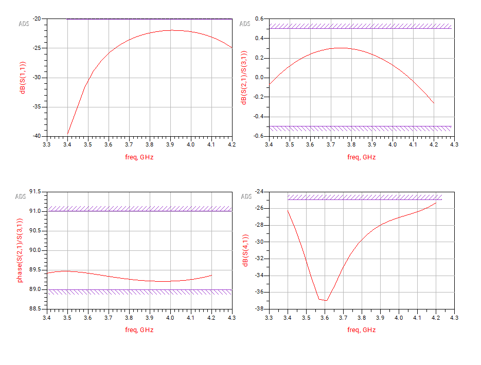
- Input Reflection (S11): Stayed below -20 dB, indicating excellent impedance matching.
- Power Split Balance (|S21/S31|): Kept within 0.5 dB, ensuring even power distribution.
- Phase Difference: Held steady at 90° ± 1°, critical for the hybrid’s functionality.
- Isolation (S41): Exceeded -25 dB, minimizing unwanted coupling.
These plots validated the design’s performance, and the Gerber files were ready for manufacturing—though, as a student project, I didn’t take it to fabrication.
Takeaways
This project was a fantastic hands-on lesson in microwave engineering. It blended theoretical design with practical considerations like substrate properties and feature size constraints. Collaborating with classmates on the Ed Discussion forum (as encouraged by Prof. Aberle) was invaluable for troubleshooting and refining my approach. Working through the iterative process—schematic to microstrip to EM simulation—really solidified my understanding of RF design tools and techniques.